Conventional Frame Wiring
|
|
|
|---|
|
Conventional Frame Wiring |
Wire Grid Reinforced Foundation |
|---|
Most of the information on this page is due to Murray McGregor, some of it is surmise by myself... If you have any further information or precise measurements, please Email those details using the button in the strap at the page bottom and I will update this page.
This information came as an offshoot to a discussion on the 'Irish List' about cocoon build up. The discussion was illustrated by Murray's words...
These 50+ year old combs seemed to have no thicker cell walls than new ones, and were thoroughly 'mucked out' by the bees each spring, as are all our old brood combs.
No-one has ever been able to shed any light on the origin of these old combs, but I was interested as they had a weird wiring pattern to them.

They were wired with straight non-crimped wires running in both vertical and horizontal directions, and welded together at the crossing points. There were several wires in each direction, all bound to thicker wires around the perimeter of the foundation. Must have been embedded hot, or with a spur embedder or similar as they would not work with electricity due to shorting.
Murray thinks that they had six vertical wires and four horizontal ones (evenly spaced), in a BS deep. (There were only BS deeps of this type). This is in addition to the heavier wires binding round the edges. The weight of wire was probably about double that used as frame wire in the UK today. He has some NZ frames that have heavier wire and it was about that gauge.
 He further thinks, but cannot swear, that the top wires and
side wires were not continuous and met at right angles, and were
welded or soldered at the corners. This would perhaps be consistent
with them having been made on some kind of jig with wire feeding in
from several reels, secured in the jig, fixed together, then the ends
trimmed, and bingo, a grid ready to embed.
Murray has no idea of the origin of these gridded combs, but he says they were good, staying nice and flat to the end of their life when it was the frames that gave rather than the comb. It has been suggested to Murray that they could be a pattern devised by an unnamed Englishman and made in the 1920's or 30's. he has also had it suggested by someone that they sounded home made, and that the 'welding' was perhaps simply soldering.
I can add that the type of wooden frame that Murray has described in further correspondence was common in the 1920's or 1930's and so the date has a high probability.
The sheets were in continuous service until 2000, when they were destroyed due to the frames collapsing in the high velocity extractor, they are known to have been in Murray's family for at least 50 years (from his father's original hive purchase in 1950), they could have been up to 30 years older even than that.
The large drawing is my 'artist's impression' of the grid and has been drawn at 2 pixels per mm, the smaller drawing indicates likely spreading and thickness reduction at resistance welded corners. I am of the opinion that such welding was used rather than soldering. Point contact of the thin wires would be incredibly weak if soft solder had been used and the time taken to solder each individual joint would have been large. By contrast a single horizontal bar electrode, placed sequentially, six times down the grid would be easy and quick. Owing to the thicker gauge of the frame of the grid this may have been fabricated, in bulk, in a separate operation. The finer grid wires being superimposed in a second run.
As far as embedding goes modern methods might opt for moulding the grid into the foundation in one operation using a sophisticated version of the Leaf Press The dies of which could be made easily on a CNC milling machine, but in 1920, or whatever, I think that the grids may well have been heated on a 'hot plate' to a very slightly higher temperature than molten wax and then pressed into plain foundation using a jig with pins, that located on the wire junctions and applied pressure evenly.
The temperature elevation above wax melting would require to be high enough for the mass of the grid multiplied by it's specific heat to provide enough heat energy to overcome the latent heat of fusion in the amount of beeswax to be melted.
Alternatively, the same sort of multi-pinned jig could be used to heat the grid electrically and at the same time provide the embedding pressure.
|
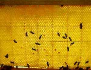
The picture at right is of a frame that has had vertical wired foundation fitted into a frame which has horizontal wiring. This is not identical to the welded grid, but it gives a good idea of it's appearance. Much conjecture, I hope someone knows some more detail. |

|
|---|
Written... 02, 03 April 2002, Addition... 03 July 2002, Upgraded... 11 May 2005,
|