Boxer Primer Removal
Berdan Primer Removal
Wamadet Instruction Leaflet
|
|
|
|
|---|
|
Boxer Primer Removal Berdan Primer Removal Wamadet Instruction Leaflet |
Hydraulic Decapping (uncapping)
|
|---|
|
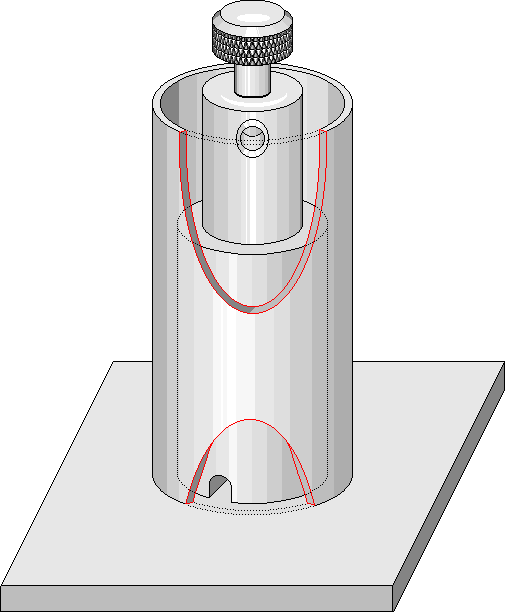
This page shows the manufacture of a 'home made' hydraulic decapper that can be made at home by those with access to a lathe and welding equipment. Or it can be used as a project by a group of shooting enthusiasts to construct a small number for sale or distribution within the group. It has been designed to be compatible, and fully interchangeable with, the hydraulic bottles that were made for use in the "Wamadet" decapping tool that was previously sold in the UK. This device is most effective if it is built of massive proportions. The extreme mass of the base unit helps to increase the effect of the blow struck on the plunger by reducing the movement due to any compliance in the supporting structure. If the device can be operated whilst standing on a blacksmith's anvil this would make the job as simple and easy as it can be. The original "Wamadet" unit came with two bottles one for small primer case types and the other for large primer types. |
|
|---|
I see no problem in redesigning bottles and plungers to suit individual calibres, but "O" rings are only available to suit three possible plunger sizes. I have collated some "O" ring sizes in a chart & dimensions with bottle and plunger dimensions for the two Wamadet sizes and an intermediate size that may be appropriate to some of you. Any alternatives that are developed by others may be Emailed for inclusion in the chart.
This picture, showing my long shafted club hammer striking the plunger is a little out of scale with the cross sectional drawing, but it shows the general principle.

|
|---|
|
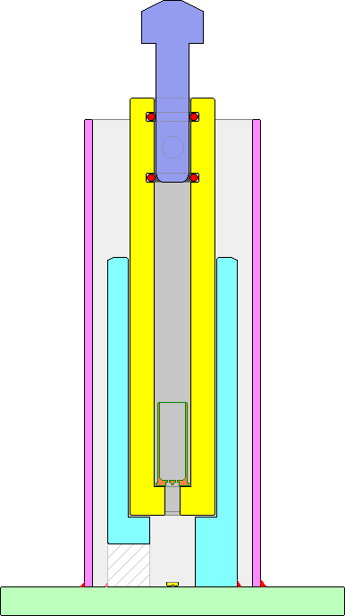
The drawing at left shows the equipment in cross section. The plunger is inserted until the lead in reduction rests on the top edge of the lower sealing ring or is inserted two or three millimetres into it. The base Plate should be about 100 mm square or larger and 6, 10, 12 or more millimetres thick.
The central pillar has a socket 85 mm deep that accepts the bottles, this boring is a nominal 1" So 25.4 mm will give a clearance on the 25.3 mm cylinders. The foot of this pillar has a channel cut into it to allow the spent primers to be removed. It needs to be solidly welded in place to resist the hammer blows. The outer tube requires continuous welding so that it will not leak. It is of such length that the water level is higher than the cross holes in the hydraulic bottles, but not so tall that the bottles cannot easily be retrieved. All bottles are 124 mm tall and 25.3 mm diameter. |
|---|
The cross sectional drawing above shows a de-capped cartridge case in position inside the bottle, but shows the plunger in the position it is placed before it is struck by the hammer. The hammer blow needs to be firm, but controlled so that it is not so violent that the underside of the plunger head crashes into the top of the cylinder.
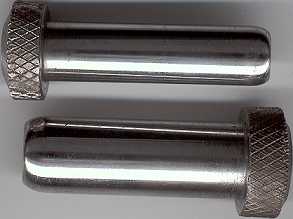
The plunger stems are 41 mm long and are highly polished. The plunger head height on the Wamadet originals were 5/16" for the small plunger and 3/8" for the large sized version. In view of damage that has occurred to the heads of my plungers, I recommend that the heads be made 12 mm. Plunger head diameter in the originals was 18 mm and 20 mm respectively, with a heavy knurl to give good grip if you are using rubber gloves. A chamfer on the crown of the plunger will minimise the swelling of the knurled portion under the constant rain of hammer blows and the thicker head will allow for re-machining if the head becomes misshapen.
|

|

|

|
|---|---|---|---|
|
Operation is as per the Wamadet Instruction Leaflet, however I recommend that you read all of these de-capping pages before you embark on the project.
|
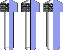
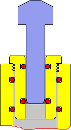
large calibre 'big game' nitro rounds or .50 Browning MG are not catered for by the bottles shown above. I see no reason why the whole equipment should not be scaled up to suit these larger calibres, but it may require a sleeved plunger to generate the pressure. (as right) By using a small plunger the surface area over which the force from the hammer blow is spread, is lower, thus generating a higher pressure per unit area. The slowing down, due to assembling and inserting the extra component, is unlikely to be a concern as such large calibres are unlikely to be handled in large quantities. The insert has a threaded portion just under the rim of the head to stop the insert rising as pressure is applied. |
|
|---|
There is a hand held tool that works on a similar hydraulic principle. This requires a special sizing die that the case is driven into, but then the case and die are filled with oil and a sealed, screw threaded, piston is entered into a seal at the top of the die and rotated to provide the pressure that expels the primer. This method may suit large calibre rounds that are not dealt with in large quantities, but I think it would be very slow when compared to the bottle method. I believe that this method is known as the Pickavant method after some hydraulic crankshaft pin removing tools used in the motorcycle industry in the 1950s.
Originated... 19 September 2002, Written... 01 to 07 October 2002, New Domain... 19 November 2003, Upgraded... 26 January 2007,
|