"E" Home
Prev. Menu

Transformer for
Drop Machine

55v + 55v Test
Transformer

Wire Gauges
ELECTRONICS
"A-Z" INDEX
Back
G8MZY logo

Electrical Transformers in Theory and Practice


During the early part of my working life I was a student apprentice at the firm of Partridge Wilson & Co Ltd., whose trade name was Davenset. During my apprenticeship I learned about various transformer devices... From 10 mm cube to items that weighed half a ton.
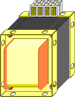
As a radio ham I have often had a requirement for transformers of types that are not available 'off the shelf' and as a result I have developed a technique of re-manufacturing existing transformers and customising them to my own use.

Basic design and construction

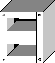
A transformer generally consists of one or more coils (winding) of conducting wire, wound on a former (bobbin) that surrounds the centre limb (sometimes all limbs) of a circuit of magnetic material (core). The winding wires are insulated and the core is made from thin sheet steel plates known as laminations (this reduces 'eddy current' losses). The assembly is held together by metal cheeks known as clamps, these clamps are held in place by long screws that are insulated from the rest of the structure (again to limit eddy currents). The winding wires are either made off to terminals mounted on the clamps or the wire may leave the coil by 'flying leads'.

A typical transformer...
The illustration
at right shows all the elements used in the construction of most transformers.

A typical transformer
Laminations

E & I, T & U Transformer Laminations
Common types of lamination are shown at left, they are known by the shape of alphabetic letter that they form. The most common type is the 'E' & 'I' form, the 'T' & 'U' is still used, but was more common in days past. The laminations are often oxidised to form a surface film of oxide that has a higher resistance than plain steel, thus isolating each layer to a certain extent and reducing eddy currents that may occur perpendicular to the plane of lamination. Sometimes one or both sides of a lamination are sprayed with lacquer for insulation purposes.
Other forms are possible and the 'F' & 'F' type shown right is one of these.

Laminations are mostly used at power distribution frequencies of 50 Hz or 60 Hz and audio frequencies, if higher frequencies (up to a hundred or so kHz) are envisaged then ferrite or other sintered iron oxide compounds are used to make solid split cores. Commonly used versions are RM Cores and ETD Cores The linked pages also give some rudimentary design details.
F & F Transformer Laminations


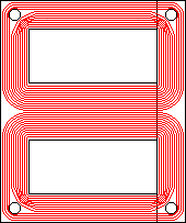
The laminations when assembled form an interleaved 'stack' or 'core'. The interleaving is usually to avoid any gaps in the magnetic circuit as air is much less permeable to magnetic flux than iron and steel.

A Stack of Laminations Forming a Core The magnetic flux runs around the two side limbs and combines in the centre limb which is twice the cross sectional area of a single side limb, thus keeping flux density constant. The flux lines that are indicated in red in the diagram at right would follow a slightly tighter path near the corner fixing holes, than my graphic skills can reproduce. It should be noticed that there is practically zero flux in the centre of the long side and fixing holes or notches are common at this point. Flux Path


The 'holes' in the core are known as 'windows' or 'window spaces' and in an assembled component they are filled by coils wound on a bobbin.

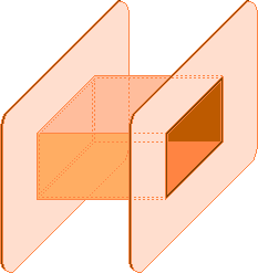
Coil formers or bobbins

Plain Bobbin
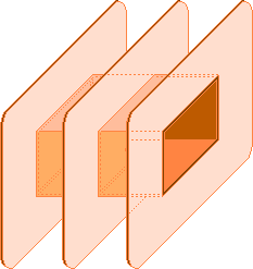
These are of two types known as 'plain' or 'split', the one shown at left is plain and the other at right is the split version.

Bobbins these days are mainly injection moulded in plastic, but larger ones often have paxolin or bakalised paper board cheeks.

Occasionally, transformers are constructed with two or more independent bobbins, each having it's own winding(s). This method of construction is rare, but has it's uses at very high voltages (above 3,000 volts).
Split Bobbin


The windings or coils that are wound around these bobbins can be either single coils or multiple ones. Single coils are a type known as 'Auto Transformers' and we will not deal any further with them on this page, as they are generally not applicable to the type of project that I get involved in.

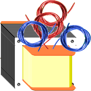
Multiple coil types are known as 'double wound' and the windings fall into two subdivisions... 'Primary' and 'Secondary' generally there is only one primary although it may be divided into two or more portions. Secondary windings may be of any number. Coils may be wound side by side on split bobbins or may be wound on top of one another with a suitable insulation between. Generally the primary or input winding is completed first as the innermost coil then layers of plastic or paper are placed over the completed primary and this is then used as a base upon which further windings are made.

Winding Coils

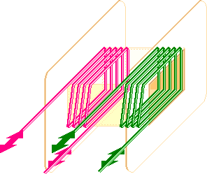
Winding directions and current flow
Two coils are shown, one crimson and one green, they indicate primary and secondary coils. An alternating current flowing in the primary coil will cause an alternating flux in the core which in turn couples with the secondary coil inducing an alternating voltage in it. If this alternating voltage is applied to a load then an alternating current will result. The ratio of turns between the primary and the secondary is proportionate (minus losses) to the voltages on primary and secondary. The number of turns per volt is a function of the cross sectional area of the magnetic circuit, the duty cycle and the allowable temperature rise. Eddy current losses are constant and the fraction of the primary current that is due to this cause is known as the 'magnetising current'. The resistive losses in the windings, due to the current flowing is generally known as 'copper loss' and is proportionate to the percentage of full load that the device is run at.

After the core and wound coils are assembled

part assembled transformer
the transformer will look some thing like this. All that remains is to add a pair of clamps and connect the wires to terminals that are mounted on one of the clamps. Testing is then performed to ensure that the specification is correct and that the finished transformer will operate safely for the rest of it's life.

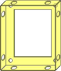
The Clamp illustrated at right has been drawn as a brass one so that it stands out against the grey page background, mostly they are of steel although aluminium and brass are sometimes used if an air gap is incorporated in the magnetic path. Brass Transformer Clamp

Insulating stepped washers

Insulated Stepped Washer This small flanged fibre washer
provides a break in any possible eddy current paths that would occur due to the fixing bolts passing perpendicular to the plane of lamination.
  Terminals

Melamine terminal blockThese are made in strips of 10 or 12 and sub divided (using a hacksaw) to provide the correct number of ways to suit the windings and tappings.
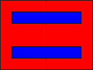

In transformers that have one winding on top of another there is sometimes a single turn of copper or aluminium foil (the ends of this turn are insulated otherwise it would be a 'shorted turn') this Faraday shield or screen is earthed and helps to suppress interference that could be transmitted from coil to coil.

Waste Free Laminations

There is a way of punching
'E' & 'I' laminations that produces a pair of 'I's from the window spaces of two 'E's.

This method utilises all of a sheet of rectangular material, hence the name... The principal is illustrated at right.
waste free punching method

This page has been selected by the SciLinks program, a service of National Science Teachers Association, whose name, service and logo are their copyright.
SciLinks home page
scilinks logo Click on this link or logo in order to understand the significance of this selection.


"E" Home
Prev. Menu
Back
Top
Email Me!

Written... Summer 2001, Revised... 09 October 2001, Revised & spellchecked... 31 Mar 2002, Additions... 01 May 2002, New Domain... 21 April 2004,

Electronics Favicon Coding Standard 2003 Issue 5